


Below method statement covers complete fire protection system installation and testing inline with any size and type of project.
References:
Manufacturers instructions
Approved fire water pump submittal.
Approved shop drawings.
Project Specifications
NFPA 20
Scope of work includes:
- Sprinkler System
- Wet Riser Piping
- Fire Pumps
List of Materials
Sprinkler pipes to ASTM A536 GR `B’
Zone Control Valve
Test and Drain Valves
Alarm valves
Pressure gauges
Flow switches
Pressure reducing valves
Water motor gong
Pump and motor assembled on a common base frame, coupled using suitable coupling arrangement by the manufacturer.
OS&Y valves, NRV, flexible connectors and piping accessories as per approved submittals.
Pump foundation as per approved drawings.
Other associated materials
Equipment / Tools Required:
Electric drilling machine
Mobile scaffold and step ladder
Mechanical tool kit
Measuring tape
Water level
Cutting tool
Grinding machine
Threading tool
Grooving machine
Digital Multimeter
Clamp Meter
The calibration certificates of testing instruments shall be verified prior to usage and copies shall be included in the test reports.
Material Storage and Handling
All material while unloading shall be lowered to the ground either manually or with mechanical aid like crane depending on the quantity of the pipe and should not be dropped to the ground.
For pipes, timber supports shall be placed beneath at equal distance.
Pipes shall be stacked on a flat surface with adequate supports.
End caps of pipes shall be in place until removed for installation.
While stacking, it shall be ensured that pipes of bigger sizes are placed below and smaller sizes on top.
All pipes shall be covered and shall not be exposed to direct sunlight.
All other items such as valves, gauges, switches shall be kept on racks within site stores and shall be segregated as per size, model, type etc. for easy retrieval.
Any items found damaged or not suitable as per project requirements shall be removed from site. If required to store temporarily, they shall be clearly marked and stored separately to prevent any inadvertent use.
Health & Safety Requirements
All precautions shall be followed as per established project safety procedures.
Warning signs shall be placed at required location during pressure testing of the pipe work and barriers where required to protect other services.
All safety regulations prevailing to this project site shall be strictly adhered to.
Ensure work area is clean and tidy.
Safety equipment (example hard hats, safety shoes, coverall gloves, goggles when necessary etc) to be worn all the times.
Ensure area is kept clear while lifting is in progress and cordon area off if necessary with warning tape.
Check all lifting equipment for visual sign of damage.
Check electric drill machine and extension leads for visual sign of damage.
Safety Officer shall check and ensure all safety measures are taken as required.
Only experienced and skilled personnel shall be engaged for start-up and commissioning of fire pumps.
Safety guards shall be in place and secured prior to start-up.
Cable test reports shall be verified prior to energisation.
Warning signs and tapes shall be placed during start-up and commissioning as required.
All safety procedures shall be followed in accordance with the project health and safety plan.
Sprinkler Piping System Installation
Check and ensure all drawings used for installation of fire sprinkler system are latest and approved for construction.
Check the coordination of piping layout with other services and reflected ceiling and resolve problems, if any.
Mark the pipe routing on the ceiling as per approved drawings.
Fix supports and hangers with approved material, as per approved layout drawings.
Cut all excess hanger rods to leave only 25mm lengths below the support for final adjustment of levels, if required.
Machine cut the pipes square to required length and ream the pipes to remove burrs and clean thoroughly before installation.

Pipe work upto 50mm shall have threaded joints and pipes 765mm and above shall be with grooved coupling joints.
The pipe work shall be grooved and installed as per coupling manufacturers instruction and grooving equipment as supplied by manufacturer shall be used.
Install pipe work at heights and to gradients shown on approved drawings, in a neat and tidy manner.
Holesaw cutter shall be used to cut holes in the pipe work where required for fixing mechanical Tees etc.
PVC Sleeves of suitable sizes shall be provided at wall crossings and fire stopping with approved material shall be completed.
Only standard fittings shall be used for changes in directions, reduction in pipe sizes, Tee joints, etc. Only long radius bends shall be used where required.
Expansion couplers shall be installed at location where piping crosses the building expansion joints (Refer Annexure-I for manufacturer’s recommendations).
All vertical pipes shall be installed plumb with at least 25mm clearance from the wall / surface.
Install valves, supervisory switches, flow switches, pressure gauges etc. as per approved drawings and manufacturer’s instruction.
Install drain valves at all low points as shown on approved drawings and ensure that water can be drained from all sections of pipe work.
Inspectors test drain valves of suitable size shall be provided at the farthest point in the system in each zone as per approved drawings.
Check and ensure easy access is available for maintenance and removal of all components such as valves, switches etc.
The droppers for sprinkler heads are installed at location as per approved layout / coordinated drawings.
Plug or cap-off all open ends in the piping during the installation phase.
Flush and clean the entire piping with clean water until the system is clean.
Install correct type of sprinkler heads as per approved drawings and manufacturers instruction.
Clean the pipe work thoroughly to remove all dirt, soil, oil, etc. and apply one coat of primer.
Provide identification and flow directional arrows to the pipe work, valves and other components as per approved submittals / details.
Entire installation shall be supervised, checked and certified by specialist supplier prior to testing and commissioning of the system.
Details of the entire installation of the system shall be inspected and approved by the Civil Defense Authority.
The entire pipe work shall be hydrostatically pressure tested as per separate method statement for fire fighting system testing and commissioning.
Wet Riser Pipes and Hose Reels Installation Methodology
Before commencing any installation of Wet Riser Piping with fittings and accessories the following activities shall be carried out by the responsible representative of the client/consultant.
Check that the approved construction drawing of current revision is readily available for installation.
Verification of material used for installation, should have an approved material submittal.
Check the type and working conditions of pipe and applicable or required fittings and accessories as per the contract specifications.
Verify the availability of all required accessories on construction SITE prior to start of any installation activity.
Loading and unloading of pipes should be carried out by hands and use of skids should be avoided. Pipes should not be dragged along rough surface. Extra care should be exercised in handling small dia pipes to avoid damage.
Check the work area as per the safety aspect; it should be clean, tidy and safe for installation of fire fighting piping systems.
Wet Riser Installation Procedure
Mark out the location of hangers and supports for fire pipes and accessories as per the approved construction drawings.
Drill the marked position for the hangers and supports by using a drill of appropriate or required size.
Fix the flush anchor at drilled position by gentle and uniform hammering. During hammering use the “Setting Tool” of appropriate size for proper grip of the anchor in concrete.
Before fixing the threaded rod, insert a washer of appropriate size in to the rod.
Fix the threaded rod of appropriate dia and length into the anchor by twisting. For easy and balancing twisting of the rod use preferably two nuts locked together and a wring spanner for tightening.


Finally fix the washer near to the slab by tightening a nut over it; this will improve the strength and load bearing capacity of threaded rod and lock the support in place.
Measure length of pipe required, make due allowance of any pipe fittings to be used. Cut the pipe to the measured length in machine, ensuring that the ends are cut square. Flame cut ends will not be used for grooving.
For pipes more than 2 ½” dia grooved joints are required. With help of grooving machine prepare grooves at the pipe end to accept the Victaulic mechanical joints fittings as per the specifications and manufacturers recommendations.
For pipe less than 2 ½” dia, threaded joint is required, for this purpose, make external threads on the pipe’s end by using proper threading machine.
After making thread, these will be covered with jute. Wrap the jute around the entire length of the threads beginning with the second number thread from the end. Then screw the threaded end of the pipe in the adjacent fitting or pipe.
After preparing threads and the grooves, check them for their proper formation and depth.
The pipe will be checked for correct level and position and if necessary adjusted on the pipe support, or re-level the pipe with spirit level and tape.
For vertically installed pipes, install wall hangers at drilled position by adopting the same procedure. Install the pipes in the clips and “U” clamps. Provide additional support, to hang each landing valve.
Refer the drawings for typical arrangement of landing valve.
Installation of Landing Valve
Mark out the location of landing valves on the pipes as per the approved construction drawing of current revision.
Provide mechanical Tee in the pipe to install the landing valve with the help of appropriate hole saw cutting machine prior to install the landing valve.
Install the “U” clamp fittings with each landing valve fitting.
Keep the canvas 2 ½” x 30 meter hose in the pre-installed metallic fire cabinet after the commissioning stage.
After completion of installation, remove burrs, dirt and construction debris and repair any damaged finishes including chips, scratches and abrasion. Make good paint finish.
After completion of installation work, work inspection request (WIR) shall be raised for Consultant’s inspection.
Hydrostatic test shall be performed as per attached format for the entire system to a pressure of 15 bars.
Specialist supplier shall supervise the installation and testing and certify the same.
Sprinkler System Testing Method
A written report shall be prepared by Fire Protection Specialist upon completion of Testing and commissioning to certify the results.
Manufacturer’s instructions, as applicable, will be followed for testing and commissioning of system components.
All the test results will be recorded in the test format, which has been prepared inline with the NFPA format. A sample test format is attached to this method statement for approval.
The sprinkler system will be tested separately for the tower area and podium areas as applicable on a project site.
For Towers:
A flow test will be conducted for sprinkler system in the tower’s floor areas.
Water flow will be established by opening the inspector test and drain valve of zone control valve assembly. The flow shall be equivalent to flow through our sprinkler head as it is pre set in test and drain valve.
Ensure that fire alarm is activated when inspectors test valve is opened, which means flow detector shall be interfaced with fire alarm system (fire signal)
Ensure that water motor gong will operate in the pump room when the pump is in running condition.
Manufacturer’s written instruction shall be followed for the testing of sprinkler.
For Podiums:
Sprinkler system in the podium area will be tested, by operating one of the upright sprinkler heads.
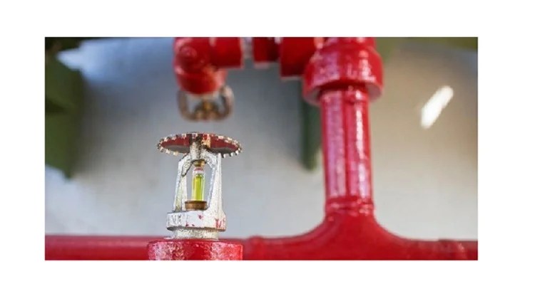
Upright sprinkler head will be operated by heating the glass bulb of the head, once the temperature reaches 79°C, the glass bulb of the sprinkler breaks and water will flow.
Ensure that fire alarm is activated when inspectors test valve is opened, which means flow detector shall be interfaced with fire alarm system (fire signal).
Ensure that water motor gong will operate in the pump room area when the pump is in running condition.
Alarm Valves Testing
Verify that auxiliary drains are closed and that the system is free of leaks.
Open the system test valve (and any auxiliary vents provided to facilitate the removal of air from the system) to allow air to escape from the system while it is filling with water.
If desired, close the alarm shut-off valve to prevent local alarms from operating while filling the system.
Slowly open the water supply main control valve.
Allow the system to completely fill with water. Allow water to flow from the system test valve and any other open vents provided until all air is exhausted from the system.
After all air is exhausted from the system, close the system test valve and all other open vents.
The pressure gauge on the system side of Alarm Check Valve Clapper should indicated water pressure equal to greater than the water pressure indicated on the gauge located on the supply side of the clapper.
OPEN the Alarm Shut-Off valve in the Alarm Valve trim, and verify that all other valves are in their normal operating position.
Secure all valves in their normal operating position.
Water Flow Detector Testing
A flow test will be conducted for water flow detector.
Water flow will be established through the inspectors test connection.
Ensure that fire alarm is activated when inspectors test valve is opened, which means flow detector shall be interfaced with fire alarm system (fire signal).
Manufacturer’s instruction shall be followed for the testing of main drain valve.
Landing Valve & Fire Hoses Testing
After completing the hydrostatic pressure testing of wet riser piping, a flow test will be conducted to ensure proper operation of the landing valve.
Unwind the 2 ½” dia fire hose and connect one end of fire hose to branch pipe and other end to the outlet of landing valve.
Slowly turn the hand wheel of the landing valve, till we get a constant flow through the branch pipe outlet.
Ensure the flow and pressure at the outlet of branch pipe.
Once the hose reel piping is under pressure and tested, a flow test will be conducted to ensure proper operation of the hose reel.
Hose Reel Testing
Unwind the hose from the hose reel, and after removing 2-3 metre of hose from the hose reel, the automatic valve will open automatically.
Open the nozzle and ensure the flow and pressure at the nozzle of the hose reel.
1” dia. PRV shall be used to maintain an outlet pressure of 4 bars.
One of the remote hose reels will be operated to measure the quantity of water discharge. The water discharged from the hose reel will be collected in a calibrated container to measure the water flow per minute to establish the flow rate which shall be 23 l/min approximately.
Fire Extinguisher Inspection & Testing
Check for physical conditions for the fire extinguisher and the pressure gauge reading of the fire extinguisher.
Inspect the fire extinguisher to determine that the hose and horn is unobstructed and the plastic tamper seal is intact. Recharge if the weight has reduced more than 5% of the extinguisher content weight.
Portable fire extinguishers supplied and installed will be inspected and checked during the commissioning period to ensure that they are in good working condition. Any extinguisher losing 10% of its nominal content by weight will be recharged to the required standard.
All cylinders containing the chemical extinguishing agents will be checked to ensure that the contents are up to the specified standards and are so marked with paint on the outside of cylinders.
A sample fire extinguisher (as selected by the Consultant) shall be discharged during fire extinguisher testing & commissioning demonstration. The discharged cylinder will be replenished as required.
Fire Water Pump Installation Methodology
When received at site, each pump, valves, air vent, pressure relief valve and water meter shall be checked for quantities, Model Nos., physical damages etc. and notify supplier of any discrepancies for suitable rectification or replacement.
Valves shall be segregated as per sizes/models and stored on racks within a covered store.
Any items found damaged or not found suitable as per the project requirements shall be quarantined. Non-compliant material shall be clearly marked and stored separately to prevent any inadvertent use until returned to vendor.
Pump shall be stored on a flat surface in well-ventilated storage area.
Inlet and outlet flange blanks shall not be removed until ready for connection to pipe work.
Manufacturer’s instructions shall be strictly followed as applicable.
If the pumps are stored for longer periods the shaft shall be periodically rotated and lubricated, if required.
The stored motor should be inspected periodically for obvious conditions such as standing water, parts theft, excess dirt buildup or any other abnormal condition.
Storekeeper will be responsible for proper storage and maintenance of records, as required.
Preparation for Fire Pump Installation
The foundations designed to meet the vibration and sound control requirements shall be provided by main/civil contractor.
Check and ensure that the shop drawings used are latest and approved for construction.
Contractor will co-ordinate the location of foundation as per approved shop drawings.
The foundation surface shall be flat and level and smoothly finished top surface.
Check the piping support locations and cable tray routing locations in co-ordination with pump and piping layout and ensure they are not obstructing the space around pump.
Ensure easy access and sufficient clearance for servicing and maintenance i.e for replacement of pump, motor.
Installation of Electric Driven Pumpset (Main & Jockey)
Mark the locations of the pump base frame and hole locations.
Drill the suitable size holes in the foundations.
The pump and motor are assembled on the base frame by suitable flexible coupling arrangement. Shift the pumps to the place of installation in safe manner. Use hand trolley / folk-lift/ crane as applicable/ required as per site conditions.
Check and ensure free rotation of the shaft.
Position the pump frame assembly on the foundation and fix the anchor fasteners.
Water level the pump assembly by placing the shim plates below the base frame as required. Gap between motor and pumps, after pump installation shall be rechecked by the pump supplier before testing.


Ensure proper coupling guards are provided.
Complete the piping and valve package installation as per approved drawings. Remove the end caps fixed on the inlet flange.
Install the electrical control panel and power connections as per approved drawings.
Incoming and outgoing cables to be insulation resistance/continuity tested.
Provide earth wiring as per approved drawings/manufacturers instruction.
Follow the manufacturer’s instructions while installing the pump.
After completion of the installation, it shall be checked and certified by the supplier/manufacturer.
After completion and fire pump installation and piping connections, the same shall be checked and certified by the pump supplier.
Request for Inspection’ shall be raised for Consultants approval.
Fire Pump Precommissining
Pre-commissioning checks prior to start-up – Mechanical
Check and inspect the installation of Fire Water Pump is complete, verify the installation as per approved drawings.
Verify compliance to the attached manufacturer’s installation instructions.
Obtain installation certification from manufacturer or their authorized representative.
Check and ensure adequate clearance available for service and maintenance of pumps and motors.
Check the installation is coordinated with other services.
Ensure the shipping bolts / chambers are removed.
Check all nuts, bolts, screws, fastners etc., are fixed and tightened as required.
Ensure the piping is pressure tested. Verify test certificates.
Check all piping connections are complete at pumps, flow meter and pressure relief line including flexible connections where applicable.
Check and ensure the piping is flushed and cleaned.
Check the alignment is completed as per manufacturer’s instructions.
Check and verify the water level in the water tank is full.
Check and ensure the safety guards are in place and secure.
Adjust desired cut-in and cut off pressure as per requirements.
Rotate the pump manually and ensure free and smooth rotation.
Ensure the pumps are cleaned prior to start-up and all identification labels and tags are in place.
Electrical Checks:
Check all power cabling and control wiring is completed and dressed neatly.
Check the power isolator is fixed close to the pump motor for emergency stop and power isolation.
Check all terminations are completed and tightened as required.
Check the grounding connections are completed and tightened as required.
Ensure the overload protections are set correctly as per the pump motor load current.
Ensure all identification tags and labeling works are complete.
Start-up and Testing of Electric Driven Fire Pump
Open suction gate valves.
Check that pumps is full of water and that all air contained in pumps has been allowed to escape through the air release valve.
Compress packing evenly with gland (Gland nut should be finger tight).
Lower setting of pressure switch (senses discharge pressure) to prevent pump from starting.
Place the main disconnect switch in the ON’ position.
Place circuitry breaker in the ON’ position and check if Power on light is illuminated.
Check direction of driver rotation by pressing momentarily the Start’ and then Stop’ push buttons on the controller (proper direction is indicated by arrow on pump casing), for in-line pump use a light on shaft to see rotation (this is clockwise looking down from top of motor). If rotation is wrong interchange motor leads in panel per instructions in panel.
Bring the timer setting down to one (1) minute for automatic start test purpose.
Open system butterfly valve.
Bleed the system by opening a valve on the pressure sensing line to create a pressure drop.
As soon as fire pump starts check if full load current valve is within the electric motor name plate rating with service factor taken into account.
Check packing adjustment to obtain slight leak of approximately 1 drop per second.
After running for one minute (time set on the running period timer), stop pump with stop button. If you try stopping it before the time set on the timer, the pump will not stop.
Bleed again until desired start-up pressure is attained.
Allow jockey pump to stop automatically at pressure switch setting.
Measure the total flow of water from the pump, at the outlet, and verify the same against the design requirements. Record the results in the commissioning format.
Testing Automatic Operation of Fire Pump
Open system butterfly valve and turn all the isolating valves to the fully open position.
Place the main disconnect switch one the ON position.
Switch fire pump circuit breaker to the ON position.
Switch the jockey pump to AUTO (the power ON light must be lit).
Record all pump and motor nameplate data in the commissioning format.
Ensure compliance to all manufacturer’s start-up and commissioning instructions, as applicable.
Attachments
Work Inspection Request (WIR)
Installation check lists signed by QA/QC
Test Certificate for Piping System / Hydrostatic Test Certificate
Testing and Commissioning certificate for sprinkler system.
Testing and Commissioning certificate for wet riser system.
Schedule of Fire Water Pumps
WIR (for Witness of start-up and commissioning) duly signed by Consultants
Signed-off pre-commissioning check lists
Fire Pump Commissioning reports
Calibration certificates of testing instruments
Installation Checklist for Fire Pumps
Check the installed pumps and accessories have approved submittals
Ensure the drawings used for installation are latest and approved
Verify the pumps and accessories are as per approved submittals.
Check the plinths and ensure the same is as per manufacturer’s requirements / approved drawings.
Installation of equipment and accessories is as per approved drawings.
Check and ensure water meter is installed as per approved drawings.
Ensure installation complies with manufacturer’s instructions.
Check all nuts, bolts, clamps etc., are fixed and secured.
Check the installation of piping is completed as per approved drawings.
Check the control panels are installed as per drawings.
Check all cable and wiring is completed and terminated.
Check and ensure adequate access available for maintenance and service including removal of components.
Check and ensure the installation complies with NFPA 20
Check the identification labels / tags are provided as per the requirement.
Ensure the equipment is cleaned and free from dust and debris.
Pre commissioning Check list for Fire Water Pumps
Check the make, model and type of the installed pump as per approved drawing and submittal.
Check the location of pumps as per approved drawings.
Ensure the method statement and test report formats are approved prior to testing and commissioning.
Check availability for access to all components for testing and commissioning.
Check shipping bolts/clamps are removed prior to start-up.
Ensure alignment is checked and completed as per manufacturer’s instructions.
Check the provisions for anti vibration as per approved details and submittals.
Check all piping connections are complete including flexible connections as per approved details.
Check all nuts, bolts, screws, etc., are secure and tightened as required.
Rotate the pump shaft manually and ensure it rotates freely.
Check the emergency manual start.
Check automatic start and stop.
Check auxiliary alarm contacts.
Check identification labels/tags are provided as per approved submittals/details.
Installation of pump/s certified by manufacturer or their authorised representative.
On initial start-up check for correct direction of rotation.
Check for any unusual noise and vibration on start-up.
Electrical Checks prior to Fire Pump Start-up
Check all cabling and control wiring is completed and tightened as required.
Check the provision of grounding as per approved drawing and details.
Check cables have been tested verify test reports prior to start-up.
Check the isolator is fixed close to pumps for emergency shutdown and maintenance, as per approved drawings.
Check the line voltage and phase rotations as per requirement prior to fire pump start-up
Ensure all identification works are complete.
Check the current drawn by pump motor is normal on initial startup.
Record all test results on approved commissioning format.